
Larry East, W1HUE
Tucson, Arizona
(contact author)
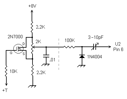
The diagram below shows the simple RIT circuit that I added to my 15M
Cub. The circuit is certainly not original, but I don't recall where I
first saw it. A 1N4004 is used as a "tuning diode" – reverse voltage
applied to it via the 2K pot varies it capacitance. (Do not use a
1N4001, …2 or …3 – they won't have sufficient capacitance range.) The
1N4004 is coupled to the oscillator via a small capacitor. I used a mini
trimmer (Digi-Key part number SG1022-ND) to allow the RIT range to be set
(a total range of 3-4 kHz is about right). However, a small fixed NP0
capacitor can also be used; 10pF will probably be required for the 20M
version, and 4.7-6.8 pF should work for other versions. The 2N7000 is
used as a switch to set the voltage on the 1N4004 to "mid range" during
transmit, thus disabling the RIT. The original circuit used an NPN
transistor switch, but the small collector-emitter voltage present when
the transistor was conducting resulted in the RIT setting slightly
effecting the transmit frequency. The very low on-resistance (less than
10 Ohms) of the 2N7000 MOSFET eliminates that problem (a J310 or similar
JFET should also work).
Note that there is no RIT on/off switch shown; if you wish to add one, use a SPDT type to switch the MOSFET gate resistor between +12V (disabled) and +T (enabled). I used a center-detent pot for the RIT control (Mouser part number 313-2000-2K) and did not find a switch necessary.
The RIT control resistance can be anything between 1K and 10K; the resistors connecting it to +8V and ground should be approximately the same value as the pot and matched to each other to within a few percent.
The components to the right of the dotted line should be mounted on the PC board using very short leads. I soldered one end of the trimmer cap to the solder pad of C6 that connects to U2 pin 6 and bent the other tab upward. The 1N4004 and 100K resistor are soldered to the upward-pointing tab, and the anode of the diode is grounded to a ground feed-through to the rear of U2. The other components are mounted on a small piece of "perf-board" attached to the RIT control.
The +T control voltage can be obtained at the junction of R21, R23 and C43; simply solder a wire to one of the component's solder pads. +8V is obtained from pin 1 of U1, the 78L08 regulator.
I mounted the RIT control in the upper left-hand corner of the front panel. The MFJ logo in that position can be easily removed, if desired, using denatured alcohol.
During initial testing, you may wish to ground the 10K resistor from the MOSFET gate rather than connecting it to +T. This will result in the RIT being enabled during transmit so that you can check the RIT range by measuring the transmit frequency. The RIT range will not be symmetrical; there will be about 20% more VFO offset on the low-frequency side than on the high side. Note that after the RIT circuit is installed, you will need to readjust L3 for the proper transmit/receive frequency range.
Good luck and enjoy!
————
Copyright © 2005, 2012 by Larry East, W1HUE ————
Page last updated on June 17, 2012