Larry East, W1HUE
Tucson, Arizona
(contact author)
This article appeared in the July 1994 issue of The QRP Quarterly.
Note: This article applies to the original W9GR DSP Audio Filter described in the September 1992 issue of QST. The modifications do not apply to later versions of the filter. The W9GR DSP-III filter, which has been available for some time, incorporates a 13-bit ADC and audio AGC obviating the need for an input limiter.
I have been intrigued for some time with the use of digital signal processing to enhance receiver performance, but have had neither the time nor spare cash required to pursue development work in this area. So, I was very interested in W9GR's QST article describing a DSP filter of his design available as a kit. I purchased the kit, and after a long wait (apparently there was much greater demand than expected and problems in obtaining parts) it arrived and I set about assembling it. Although it worked quite well (first time it was powered-up, even!), it did have a few irritating characteristics:
Not being one to resist mucking about inside my radio equipment – even new pieces of equipment – I set about to see what I could do to improve on the situation.
The first problem was easily corrected: I simply replaced the original LF347 quad op-amp IC (used for analog audio conditioning before and after digital processing) with an LM348 IC. It appears that some sort of momentary instability was occurring in the original IC when the supply voltage was ramped up or down.
The noise problem was a little harder to solve. It should be noted that the kit I received had a revised PC board layout that was supposed to eliminate noise problems present in earlier versions. Also, bypass capacitors were installed on power input, audio input, speaker and headphone output connectors, and the unit was built in a metal box as suggested in the kit instructions. Although the noise was not excessive, I still found it annoying; particularly when using one of the CW filter modes with no (or very little) input audio present. I was finally able to reduce the noise to a very low level by making the following simple modifications:
A few words are perhaps in order concerning the unit's limited dynamic range: first of all, it is due to the use of 8-bit analog-to-digital (A/D) and digital-to-analog (D/A) conversion for the sake of economy. As noted in the instructions included with the kit, it is important that the input audio level be kept in the upper portion of this 8-bit range in order to keep the A/D and D/A conversion precision high and quantizing noise low. If the audio level is too high, the A/D will "wrap around" resulting is severely distorted audio. In order to maintain the proper input level, the radio feeding the filter needs to have a "flat" AGC characteristic. Well, fancy new state-of-the-art supper whizbang rigs may have flat AGC's, but my QRP rigs and old FT-301 don't! I was therefore continually "diddling" the receiver audio output in order to maintain the proper audio level into the DSP unit. This tended to distract from the otherwise great performance of the unit; the CW filters are absolutely "brick wall" with no ringing, and the automatic notch and noise filter modes actually makes 40m SSB bearable at night!
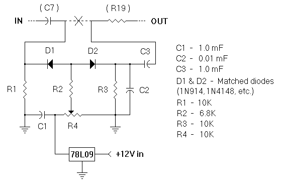
I finally solved the problem by adding a simple series limiter ahead of the analog-to-digital converter, as shown in Fig. 1. In the following description, part numbers enclosed in parentheses refer to original DSP parts; other part numbers refer to the limiter circuit. This simple circuit limits the amplitude of the audio signal to the A/D, thereby eliminating distortion due to A/D "wrap around". The clipping level is set by R4; diodes D1 and D2 should be well matched so that positive and negative signal peaks are limited at the same level. Matching can also be accomplished by selecting the value of R3 (and/or R1) to produce equal DC voltage drops across the two diodes (should be matched to within 0.05V). The 78L09 regulator provides a fixed reference voltage for the limiter eliminating the necessity to reset the limit point if the supply voltage should change. The regulator can be eliminated and R4 connected directly to +12V if the filter will always be used with the same regulated power source. I built the limiter on a small piece of perf-board and mounted it "spider web" style above (U2). A miniature trim-pot and small 25V ceramic caps were used to keep size to a minimum. Connections were made without modifying the PC board by unsoldering the end of (R19) originally connected to (C7), and connecting it to C3 on the perf-board. A short jumper was then connected from the junction of D1 and R1 on the perf-board to the solder pad on the PC board from which the end of (R19) was lifted. A ground connection can be made to a ground trace on the top of the PC board near (U2), and +12V can be obtained by soldering a jumper to the end of (L2) nearest the front of the PC board.

Figure 1. Series limiter added between input analog filter
and analog-to-digital converter. (C7) and (R19) refer to original W9GR
DSP filter components.
The limiter is adjusted as follows:
This simple limiter circuit can, of course, be used with other DSP units
that do not have builtin protection against A/D overload.
————
Copyright © 2005, 2012 by Larry East, W1HUE ————

Page last updated on June 17, 2012