
Larry East, W1HUE
Tucson, Arizona
(contact author)
This article originally appeared in the Winter 2003 issue of the ARCI
QRP Quarterly.
A correction was published in the Fall 2005 QRP Quarterly.
A few years ago, I wrote a series of articles for the ARCI QRP Quarterly describing modifications that I had made to my Index Labs QRP-PLUS [1-5]. In between traveling, building an Elecraft K2 and editing articles for the QRP Quarterly, I have continued to fiddle with and tweak my little QRP+ – and yes, I’ve even used in on the air from time to time! In the process, I made some additional modifications that may be of interest to others:
The first two are applicable only to the "original" version of the QRP+, not the later "new improved" version. The third one can be applied to either version.
These changes are the result of much experimenting and provide improved stability, better looking two-tone SSB waveforms and the elimination of some minor transmitter spurs. These changes are not applicable to the "new improved" version of the QRP+ which uses a different pre-driver circuit. These changes are made to the RF board (the top one in the stack).
After these changes were made, the 56 pF cap that I had previously added from the collector of Q10 to ground to reduce transmitter spurs [2] was no longer required.
This section describes the revised circuit published in the Fall 2005 QRP Quarterly [7].
I had been aware of a slight "raspyness" in the transmitted SSB signal at power levels above about 2W. (This can be seen on an oscilloscope as a small amplitude modulation of the transmitted waveform when a single-tone is feed into the microphone input.) I had attributed this to some sort of RF feedback – possibly into the mic preamp – but I was never able to find the cause. However, when this was still present during tests of a new PA mounted external to the QRP+ and operated from a separate lead to the power supply, I decided that perhaps it originated in the ALC circuit. Sure enough – increasing the "hold time" of the RF detector used to control the variable gain amp before the SSB mixer fixed the problem! While I was at it, I added a small trimpot to set the SSB power level.
The ALC RF detector is located on the XMTR board (the bottom board in the stack) and consists of a resistive voltage divider (R15 and R16), a 1N4148 diode (D8) and a 0.01 uF capacitor (C37). The resulting rectified RF is feed through a 1K resistor to the base of Q7. The emitter of Q7 provides the ALC control voltage, which is also used to drive the power meter. A 4.7 uF capacitor, C38, at the base of Q7 provides some "hold time" for the ALC control voltage. In the mod described in my 2003 article, I increased the value of C38 to 100 uF and replaced the 1K resistor with a 1N5711 Shottky diode. My improved circuit uses an emitter follower to drive the base of Q7, as shown in the schematic in Figure 1. The emitter of Q7 drives the control input (pin 2) of an MC3340 variable gain amplifier/attenuator, U2, located on the AF board to control maximum SSB peak power level. In some previous mod I had reduced the value of C12 (between U2 pin 2 and ground) on the AF board from 10uF to 1uF. The reason for that change is no longer in my memory banks… The original value of C12 would probably work OK, but since the ALC circuit shown in Figure 1 works beautifully as-is, I left it alone.
Figure 1. Modified ALC RF Detector.
I mentioned that the ALC voltage also drives the output power meter. An unanticipated benefit of increasing the ALC hold time is that the meter now gives a more realistic indication of SSB peak envelope power.
The "new improved" version of the QRP-PLUS uses a different (and more sophisticated) ALC circuit on the AF board. The RF detector, consisting of D8, Q7 and associated components on the XMTR board, is essentially the same in both versions. In the newer version, both the CW and SSB power levels are set by the "power control" on the rear panel and there is no mic gain control. In simple terms, the peak power output is adjusted automatically so that the ALC voltage never exceeds a reference level established by the power control. In the "original" version of the rig (the one that I have), the power control sets the CW power level only and the ALC voltage is used to limit the peak SSB power level.
Would my RF detector modification be beneficial to the "new improved" QRP-PLUS? The simple answer is "well, it probably wouldn’t cause any harm." To really answer this question, you need to inspect the transmitter RF output on a ‘scope. Look for SSB audio peak overshot (or overshoot of the first CW element when keying the rig) or low level amplitude modulation of the SSB waveform when a single tone (e.g., whistling into the mic) is present. If you find both problems when testing your rig, then you should definitely consider doing the mod. If you see overshoot but no amplitude modulation, then adding an emitter follower before Q7 should help but you don’t need to increase C38 unless you want to add hang time to the power meter response.
If you decide to install the mod, you will need to use a ‘scope to properly set the SSB power level in an "original" QRP-PLUS. If yours is a "new improved" version, you can get by without a ‘scope but using one to view the output RF envelope is the only way to really determine if everything is working properly. Still want to do it? OK, here’s a step-by-step procedure that should keep you out of trouble:
![]() Note: If your rig has the stock IRF510 MOSFET
final amplifier, it may not be capable of delivering more than two or three
Watts P.E.P. of undistorted SSB output, especially on 12M and 10M.
Note: If your rig has the stock IRF510 MOSFET
final amplifier, it may not be capable of delivering more than two or three
Watts P.E.P. of undistorted SSB output, especially on 12M and 10M.
When you are satisfied with the power level and mic gain settings, button up the rig and give it an on-the-air test. If you have done everything correctly, you should receive complements on your nice sounding rig! If not, then well… it’s back to the bench for more tests. But I’m sure that won’t be necessary!
In its stock configuration, my QRP+ was not capable of producing more than about 3W of undistorted SSB output (less on 10-12M). I replaced the stock IRF510 MOSFET final amplifier with a Motorola MTP3055E Power MOSFET [2,3]. With that mod, I was able to get relatively clean 7W of SSB output on the low bands and 5W on 10M. However, the MTP3055 idling current was quite temperature dependent, which prompted an additional mod [5]. The MTP3055 amp still has some shortcomings that are also present in the original IRF510 amp: the linearity degrades when the supply voltage drops below about 13V [8] and the efficiency is poor.
I should mention that some people have not been able to duplicate my results with the MTP3055 final; apparently not all MTP3055’s are created equal! To compound the problem, Motorola quit producing the "E" version and the newer "V" version does not appear to have the same RF characteristics.
A few years back, the German QRP club made available a compact 5-10W linear amplifier "semi-kit", called the DL-QRP-PA [9]. The kit was designed by Helmut Seifert, DL2AVH. It uses surface mounted capacitors and resistors that are pre-mounted on the PC board – all the builder has to do is wind a couple of small transformers and mount the power transistors and a capacitor. The amplifier includes a driver transistor, has about 37 dB of gain, and exhibits very flat response from 2-30 MHz. The PC board is only 1-3/8 in. X 1-3/16 in. The mounting tabs of four TO220 transistors extend a little beyond the board, for an overall length of about 2-in.
I purchased a DL-QRP-PA kit in the spring of 2000 with the idea of possibly using it in my QRP+ in place of the MOSFET PA. The completed QRP-PA will just fit on the inside of the QRP+ rear panel between the RF output connector and the fuse holder. Unfortunately, I was already using this space for a "tune" switch and a rear panel external speaker jack. I was also a bit concerned about possible RF feedback to low-level circuits on the RF board if the PA was located so close to it. That apparently is not a problem as Peter Zenker, DL2FI, has successfully mounted the PA in this location in several QRP+’s. So this is the way to go if you want to try this PA and don’t want to make the rather drastic physical changes to the XMIT board described below.
I decided that the "proper" place for the new PA was close to the LP filters on the XMIT board. But there was no place to mount it without doing some major surgery to the XMIT board – like cutting a chunk of it out to fit over the PA mounted on the bottom of the QRP+ case. Well, after procrastinating for a couple of years, that is exactly what I did! I did not have to destroy my working XMIT board with all of its modifications, including the MTP3055E final, as I was able to acquire a "spare" XMIT board. It turned out that this "spare" had been subjected to reverse polarity, and about the only items on it that were still usable were the relays and low pass filters! Yes, there is a reverse connected diode – a 1N4001 – on the +12V line on the XMIT board, but the fuse ahead of it is rated at 3A. One guess as to which blows first when polarity is reversed – the 1A diode or the 3A fuse! [1]
Figure 2. The DL Amplifier board mounted in the bottom right hand corner of the QRP+ case (see text for alternate mounting position that does not require modification to the QRP+ XMIT board). I used a surface mount 33 uF tantalum bypass capacitor (to the right of the transformer seen in the lower part of the figure) in place of the electrolytic lead-mount cap supplied with the kit.
The PA board is mounted via the tabs on four TO220 transistors (two 2SC1971’s used in the final on one end of the board, a 2SC1970 driver and a BD242 power transistor used for bias stabilization on the opposite end). I mounted the PA board on the bottom of the QRP+ case in the rear right-hand corner (see Figure 2). I inserted a thin sheet of aluminum under the PA transistor mounting tabs and epoxied it to the bottom of the case for better heat transfer. Figure 3 shows the modified XMIT board. All components (except the LP filters, relays, relay switching transistors and U1 [10]) associated with the final and driver stages were removed and a section cut from the board to fit over the new PA board.
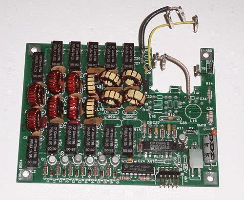
Figure 3A. The QRP+ XMIT board modified to fit over the DL
amplifier board (see Figure 2).
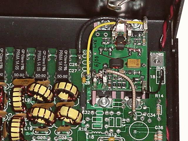
Figure 3B. QRP+ XMIT board in position and connected to the DL amp board. (This figure was not included in my original article.)
Connecting the new PA to the QRP+ is quite simple as shown in Figure 4. The 33 and 22 Ohm resistors comprise an attenuator to help prevent overdriving the new PA and provide a low impedance load to the pre-driver (Q10) on the RF board. The inductor across the 33 Ohm resistor compensates for the reduced output of the pre-driver on 160M and may not be required in all cases. The input attenuator and switching transistor for the PA "Enable" input are mounted in spaces vacated by other components on the XMIT board. Short jumpers provide connections between the XMIT and PA boards (see Figure 3).
Figure 4. DL-QRP-PA to QRP+ Interconnections.
The results? Outstanding! With a supply voltage of 13.6V, my new PA is linear to 7-8 W output on the low bands and to about 6W on 10M. I set the trimpot in my modified RF detector (see Figure 1) to give 5W PEP SSB output.
The efficiency and linearity of this little amp are definitely better than obtained with either the original IRF510 PA or my MTP3055 PA. An additional benefit is improved second harmonic suppression due to the push-pull configuration of the new PA. With the stock QRP+ output filters, all harmonics are down by more than 40dB – definitely not the case with the single-ended MOSFET PA [2]. All out-of-band transmitter "spurs" are reduced by a few dB compared to my MOSFET PA; I attribute this to better linearity of the new PA. The spectrum analyzer that I am now using does not have sufficient resolution to see the 12M "close-in" spurs, but indirect measurements using a calibrated signal generator and my K2 receiver indicate that they are also down by a few dB.
This little PA can, of course, be used with any version of the QRP+. If used with the "new improved" version, be careful not to overdrive the little amp on SSB. You should initially check the SSB waveform on a ‘scope to determine the point at which compression ("peak flattening") sets in and always operate below that power level. You can most easily monitor the SSB output power using a "QRP capable" peak-reading Wattmeter [11].
If you are considering replacing the MOSFET PA with a DL-QRP-PA, I suggest that you take the easy way out and mount the PA board on the inside rear panel of the QRP+ between the antenna connector and fuse holder. In this case, the only components that need to be removed from the XMIT board are the driver and final transistors and the output coupling caps, C25-C26. The PA input attenuator resistors can be installed on the RF board between the predriver output (Q10) and J5, and a shielded jumper connected directly from J5 to the PA RF input. Connect the PA output directly to the LPF input relay bank on the XMIT board (a blocking cap is not required) using RG-175 or similar shielded cable. The "Enable" input on the PA can be connected directly to the "+R" line on the RF board rather than from the "+T" line via a transistor switch. Power for the PA should be obtained from the +12V bus on the XMIT board to minimize voltage drop and the possibility of RF feedback.
————
Copyright © 2005, 2012 by Larry East, W1HUE ————
Page last updated on June 21, 2012