
Larry East, W1HUE
Tucson, Arizona
(contact author)
Some of this information appeared in the October 1998 QRP Quarterly.
I couldn’t resist the recent (summer ’98) TechAmerica
sale price of $99.97 for a SAMLEX model PSA-305 0-30V bench supply (regular
price $199.95). I’d never heard of "SAMLEX", but I decided to take a chance
placed an order for one – but I did wonder if I would be getting a poorly
built unit at such a low price. About a week later, UPS delivered a heavy
package containing the power supply. I was relieved to discover a
reasonably well built and apparently heavy-duty unit. It contained a hefty
transformer and pass transistors mounted on a large heat sink on the rear
panel. As an indication of its apparent ruggedness, the two pass transistors
are 2N3055’s with a peak collector current rating of 15A each.
However, I did find a few “warts”:
I decided I could live with the less than laboratory quality output regulation, but the other two annoyances had to go! The output “overshoot” that occurs when switching off the power is certainly not a good thing when testing low current devices that might be damaged if subjected to higher than rated voltage. The over-current sense circuit is so sensitive that the momentary surge produced by filter caps in a device (such as my QRP+ or my HW-9) connected to the PS will cause it to trip when the device is switched on. This problem can be worked around by turning on the connected device before turning on the power supply, but that is not a good practice in my opinion — particularly with a variable voltage PS.
No schematic (or manual, for that matter) came with the unit, but I obtained a customer service number for SAMLEX from TechAmerica and was able to talk them out of a schematic.
The PSA-305 has no internal bleeder resistor to discharge the filter caps; this is the main cause of the voltage “overshoot” when the unit is switched off. I found that the problem could be almost eliminated by connecting a 100 Ohm 10W resistor across the filter caps. However, at voltages settings of less than about 5V, some overshoot remained. The final cure was a combination of the bleeder resistor and a larger filter cap in the voltage reference circuit. The over-current sensitivity problem was cured by changing a couple of caps in the current sense circuit.
To perform the modifications described below, the following parts are required (with the possible exception of the hardware items, they are available from Radio Shack):
Remove the cover from the power supply and you will see three circuit boards secured by right-angle brackets riveted to the bottom of the case. The over-current sense circuit is located on the small PC board nearest the front of the PS (below and behind the current meter). This board must be removed; the easiest way to do this is to drill out the rivets from the bottom using a 1/8 in. (or slightly larger) drill bit. The connecting wires do NOT need to be removed from the board.
Locate the two electrolytic caps along the top edge of the board; these should be 1uF or 2.2uF. (It's possible that two 1uF caps are used in parallel at each position — in other words, four caps in place of two.) Replace these caps with 47uF 35V caps. This will introduce enough delay in the circuit to keep it from triggering on short duration current surges.
When the sense circuit trips, the power switch must be turned off in order to reset it. Resetting is almost instantaneous, resulting in voltage appearing at the PS output as soon as the power is switched off due to the charge on the filter caps. The reset time delay can be increased by replacing the cap near the center of the board — probably 4.7uF — with a larger one. I found that 100uF produced a delay of about two seconds. (If you don’t mind the instantaneous resetting, then don’t bother to replace this cap.) This cap must be able to withstand about 40V, so do NOT use a 35V cap here! (It would probably work, but why chance it…)
NOTE: Be sure to note the polarity of the caps before removing the old ones as the board id poorly marked. Also, be careful in removing the caps as the board is not particularly rugged and the solder pads can be easily destroyed.
After replacing the caps, remount the board using two 6-32 machine screws. (You may have to enlarge the holes in the mounting brackets slightly.)
This modification is made to the PC board located in the rear left-hand corner of the unit (it contains a large heat sink attached to a rectifier block – in case you have problems telling right from left!). Remove this board by drilling out the rivets. Again, you do not need to remove the connecting wires.
Looking at about the center of the board along the bottom edge, you should find a 100uF filter cap (it’s located near a diode and a transistor). Parallel this cap with another 100uF 50V cap soldered to the rear of the board. (If you can find a 220uF 50V cap that will fit in place of the original 100uF cap, you can just replace it. Just make sure the replacement cap is rated for at least 40V.)
Locate the two wires (probably red) just above the two power resistors (near the top of the board) that connect to the 2N3055 pass transistor emitters (the transistors are located on the rear panel heatsink). One end of the 100 Ohm 10W bleeder resistor connects to this point. Or better yet, connect it to the positive end of the filter caps (C2 and C3). See note added June, 2023. Now look at the back of the board and find the large solder pad to which the bottom (negative) leads of the two large filter capacitors (one on each side of the board) are soldered. This is the other point of connection. Mount the 100-Ohm resistor on the rear panel heatsink (away from the pass transistors) by making a little right angle bracket from a thin strip of metal. Drill a hole in the bracket and a threaded hole in the heat sink for a 6-32 machine screw and mount the bracket. Use flexible (insulated) wires to connect the resistor to the circuit board.
NOTE: The power supply’s output is completely floating (the negative side is NOT connected to case ground), so DO NOT just connect the bottom end of the bleeder resistor to the case!
Remount the board using a couple of 6-32 machine screws and you are finished!
After completing the above modifications, you should note the following improvements:
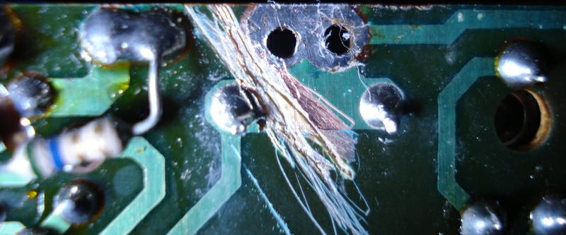
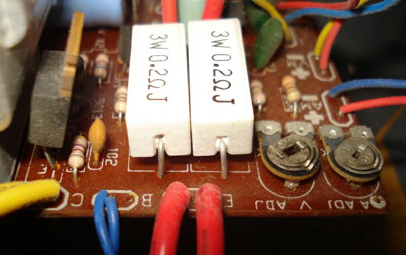
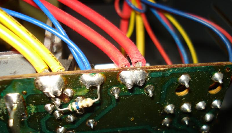
Note added June, 2023:
Steven, KJ6STF, sent me an email pointing out a
possible circuit board error in some units – the emitters of Q2 and Q7
should not be connected together. He writes: “Cut
the etch at the side where the red wires (Emitter) connect so they aren't
in parallel. Solder the red wires ON THE COMPONENT SIDE 1 each to the leads
of the Emitter resistors (not the etch). This allows each Emitter to have
it’s own resistor so the current will be evenly shared between the
2 transistors and one won’t hog current and burn up.” See the photos
below. The second and third show the two sides of the board before the
modification.
He also suggests that the bleeder resistor should be connected across the filter
caps (C2 and C3 one on each side of the boar) rather
than the power supply output. I do not believe that it really makes that
much difference. However, to make the mod described in this note, you will
need to remove the bleeder resistor connection that you may have previously
made to the emitters of the pass transistors, so go ahead and reconnect it
to the positive end of the filter caps.
Go back.
————
Copyright © 2005, 2023 by Larry East, W1HUE ————
Page last updated on June 11, 2023